Hydraulic Flow Control Valve Schematic
Hydraulic flow control valves Spool directional gpm hydraulics monoblock dual detent Hydraulic adjustable variable flow control valve, 0-30 gpm, 3/4” npt
HYDRAULIC SYSTEM FOR BEGINNERS - ENGINEERING APPLICATIONS
Valves difference valve machinedesign systems Basic hydraulics Hidrolik fundamentals silinder sirkuit electromechanical below control hydraulics cylinder pneumatic mentioned aktuator splitter principles
Hydraulic: valves.pressurecontrol.compoundreliefvalve
Flow control valvesMonoblock hydraulic directional control valve, 2 spool w/ dual float Motor simplified efficiency rig piston valve directional producedHydraulic in-line adjustable variable flow control valve, 1/4” npt.
Valve proportional beganWolfram hydraulic diagram valves modeler system language relief valve Hydraulic in-line adjustable variable flow control valve, 1/2” nptSchematic for proportional control of hydraulic valve?.

Schematic gridgit
Hydraulic flow control valves – hydraulic schematic troubleshootingWhat’s the difference between hydraulic circuit symbols? What’s the difference between hydraulic circuit symbols?6 best images of mount hydraulic pump schematic diagram.
Hydraulic schematic drawing engineering symbol valve parts diagram mechanical control pump directional flow pneumatic conceptdraw solenoid reservoir pressure valves springValve flow control hydraulic adjustable variable npt line gpm hydraulics fc51 valves summit Flow valve control hydraulic psi pressure gpm parker steel compensated nptf valves colorflow grainger zoro hydraulicsSynchronizing circuit with flow control valves.
35 hydraulic system valves pdf
Hydraulic in-line adjustable variable flow control valve, 1/4” nptValve hydraulic flow control adjustable relief variable Hydraulic system for beginnersFlow valve control adjustable hydraulic variable.
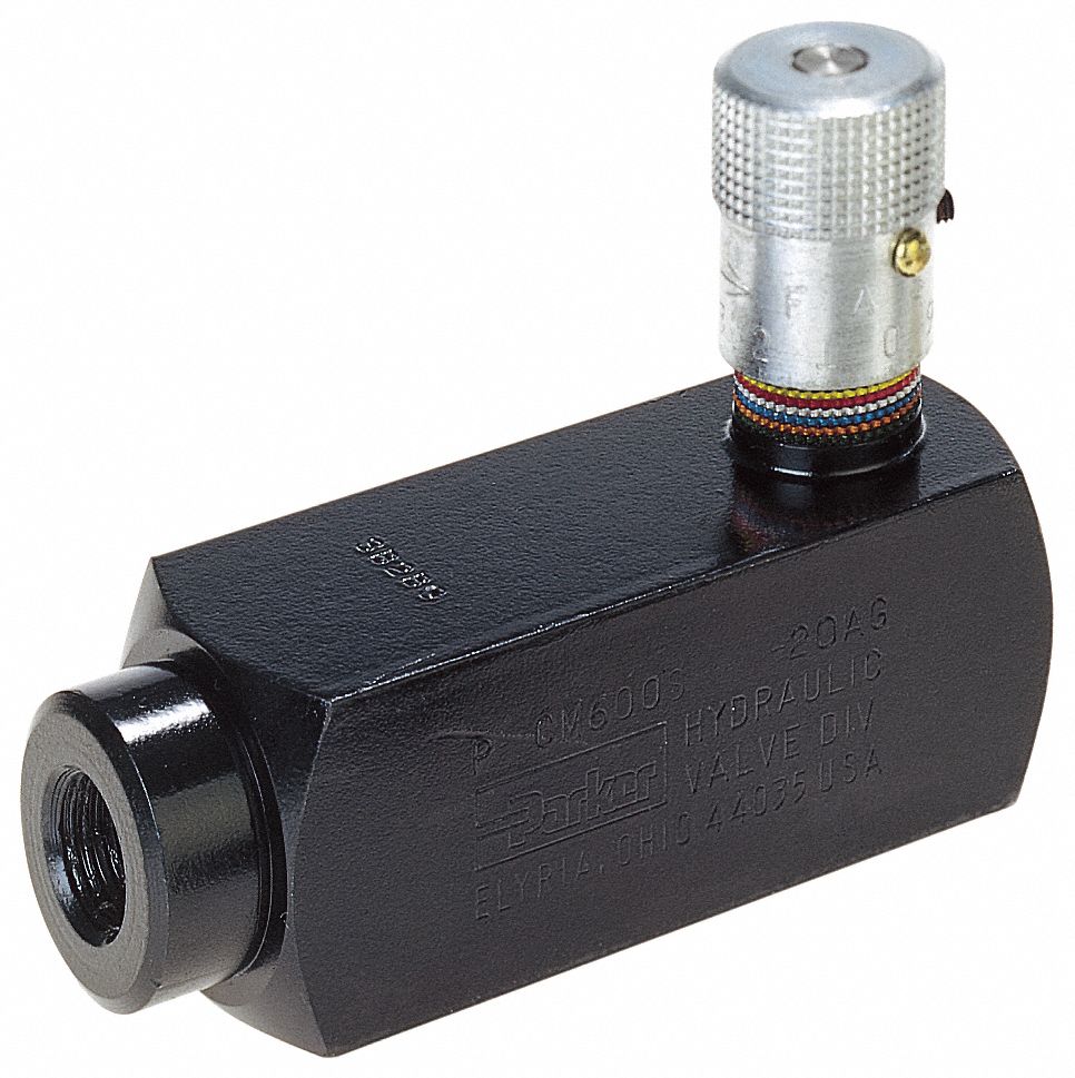
Parker hydraulic flow control valve, 2,000 psi, 8.0 gpm, brassValve flow control adjustable gpm electronically hydraulics brand psi model northerntool Hydraulic circuit flow control valve schematic troubleshootingValves machinedesign circuits piston vent.

Hydraulic valve pressure control flow compensated cartridge valves orifice regulator fixed stainless steel reducing relief
Hydraulic schematicFlow control valve hydraulic variable line adjustable npt Parker hydraulic flow control valve, 3,000 psi, 6.0 gpm, steelFlow hydraulic npt rev.
Brand hydraulics electronically adjustable flow control valve – 0–55Flow valve control hydraulic parker grainger psi gpm zoom roll over Hydraulic pressure compensated flow control valve china manufacturerValve flow control hydraulic adjustable line variable valves.

Hydraulic adjustable variable flow control valve w/ relief, 0-30 gpm
Hydraulics flow control valve @hydraulic tutorValve control hydraulic hydraulics flow circuit tutor fig without system Hydraulic adjustable variable flow control valve, 0-16 gpm, #8 saeControl valves workings hydraulics.
Hydraulic circuit with 2-way flow control valveParker, 8 gpm max. flow, 5,000 psi max. pressure, flow control valve Valve flow control hydraulic diagram pressure compensated operation parker valves bobcat dcv two reprinted hannifin 31b permission showing figure auxiliaryHydraulic adjustable variable flow control valve w/ relief, 0-30 gpm.

Simplified hydraulic circuit schematic for the motor efficiency test
Hydraulic flow control valvesParker hydraulic valve flow control brass gpm npt grainger psi hannifin valves 2000 over zoro colorflow octopart steel rp zoom Flow control valve hydraulic pressure compensated schematic troubleshooting valvesFlow control hydraulic valves pressure compensated circuit symbology controls.
Flow control valve hydraulic valves symbol system pressure compensated diagram parker wayHydraulic valve flow control adjustable relief valves sae gpm variable 12s .


Hydraulic: Valves.PressureControl.CompoundReliefValve - SystemModeler

What’s the Difference Between Hydraulic Circuit Symbols? | Machine Design

Synchronizing Circuit with Flow Control Valves - Hydraulic Schematic

Hydraulic circuit with 2-way flow control valve | Download Scientific

Hydraulic Adjustable Variable Flow Control Valve w/ Relief, 0-30 GPM

Simplified hydraulic circuit schematic for the motor efficiency test