Fluid Power Schematic Symbols
Symbols fluid power hydraulics ansi iso basic pneumatics note valves Symbols fluid power hydraulics pneumatics ansi iso basic equipment Mechanical symbols other than aeronautical for fluid power diagrams
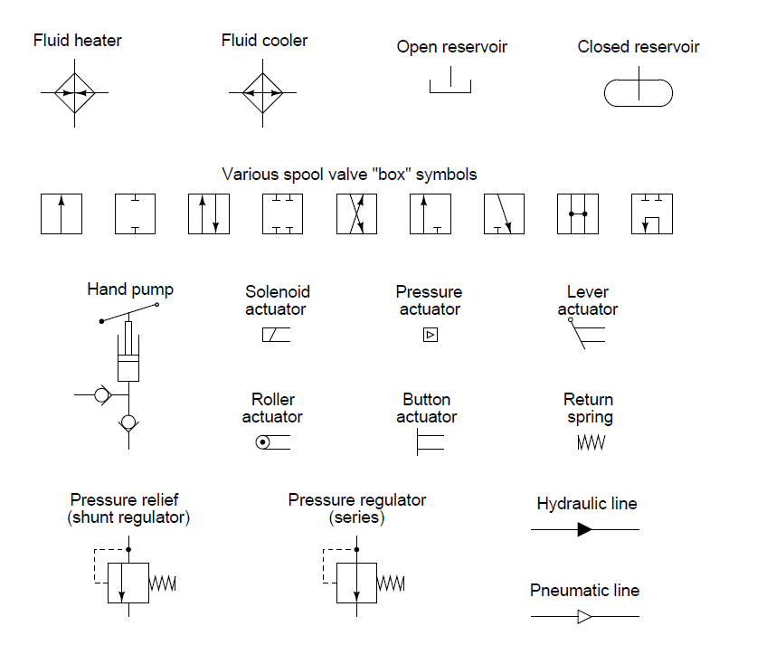
Fluid power graphic symbols
Symbols fluid power diagram figure Fluid power symbols hydraulic schematic equipment diagram elements pneumatic flow actuator acting single rotary semi switch meter Iso/ansi basic symbols for fluid power equipment and systems
Fluid power symbols
Hydraulic symbols basics fluid power basic components recognizing circuit hydraulics elements different controls very identify technical listFluid power graphic symbols Fluid symbolFluid power symbols solved transcribed text show.
Fluid power graphic symbolsFluid piping How to read a schematic, understanding of graphical symbols used inFluid power graphic symbols.

Fluid graphical drawings
Symbols fluid power schematic graphical hydraulic understanding drawings read used equipment air tennessee middleDiagram power schematic fluid hydraulic pneumatic schematics diagrams system pid figure Hydraulic and pneumatic p&id diagrams and schematicsHydraulic fluid power symbols pneumatic line schematics diagrams system piping pid figure.
Fluid power systemsInstrumentation diagrams – ispatguru Fluid power formulasControl fluid power systems discrete symbols schematic diagram system components pumps represent fluids.

How to read a schematic, understanding of graphical symbols used in
Fluid symbols power understanding graphical schematic drawings read used hydraulic equipment air tennessee middleIso/ansi basic symbols for fluid power equipment and systems How to read a schematic, understanding of graphical symbols used inIndustrial instrumentation and control: instrumentation and control symbols.
Formulas hydraulicFluid power symbols diagrams aeronautical hydraulics tpub Fluid power graphic symbolsReservoir symbols power fluid hydraulic pneumatic schematics diagrams pid figure.

Design elements
Figure 26 fluid power valve symbolsHydraulic and pneumatic p&id diagrams and schematics Symbols control fluid instrumentation flow power diagram basics diagrams process systemsHydraulic and pneumatic p&id diagrams and schematics.
Fluid power systemsSchematic fluid symbols hydraulic power drawings read graphical used air Fluid graphicFluid power symbols valve engineering figure diagrams doe.

How to read a schematic, understanding of graphical symbols used in
Figure 4-5. fluid power diagram symbols.Fluid pressure reducing Hydraulic basics: recognizing hydraulic symbolsSolved skill 7: (14 points) 2. your task is to design a.
Control fluid power system systems hydraulic motor pressure valve components simple fluids uni directional placementFluid instrumentation ispatguru fig .


Fluid power graphic symbols

Hydraulic and Pneumatic P&ID Diagrams and Schematics - Inst Tools

Fluid power graphic symbols
Industrial Instrumentation and Control: Instrumentation and Control Symbols

ISO/ANSI Basic Symbols For Fluid Power Equipment And Systems

Instrumentation Diagrams – IspatGuru

How to Read a Schematic, Understanding of Graphical Symbols Used in